SeniorSafe
Northwestern IEEE Technical Program, Spring 2024
View code on GitHub ↗︎- Wearable Technology
- Health Monitoring
- Embedded Systems
- Sensor Integration
- PCB Design
The problem
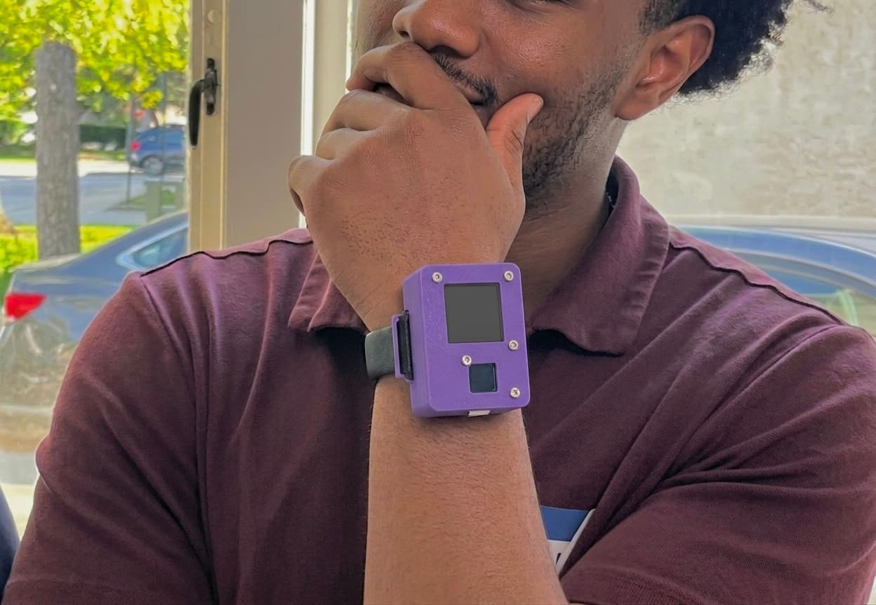
Tens of millions of falls are reported among older adults each year, but mainstream health wearables pack in sensors and screens that are hard for seniors to operate. SeniorSafe is a wearable built around a simpler feature set rather than trying to be a general-purpose smartwatch.
Design constraints and requirements
The target user shaped almost every interface decision. Instead of a touchscreen menu, help-calling is a single long-press on a capacitive touch pad that's hard to trigger by accident but doesn't require navigating a UI. Feedback runs through a haptic motor and a simple display. If a fall is detected or vitals cross a danger threshold, the system escalates on an alert path without the need for user action under stress.
System architecture
An ESP-WROOM-32 MCU ties together three sensing inputs and two outputs.
Inputs:
- MAX86916 optical (PPG) sensor — heart rate & blood oxygen
- MXC6655XA 3-axis accelerometer — motion detection
- AT42QT1012 capacitive touch sensor — panic button & cancellation
Outputs:
- 1.3" TFT display
- Haptic motor
Features
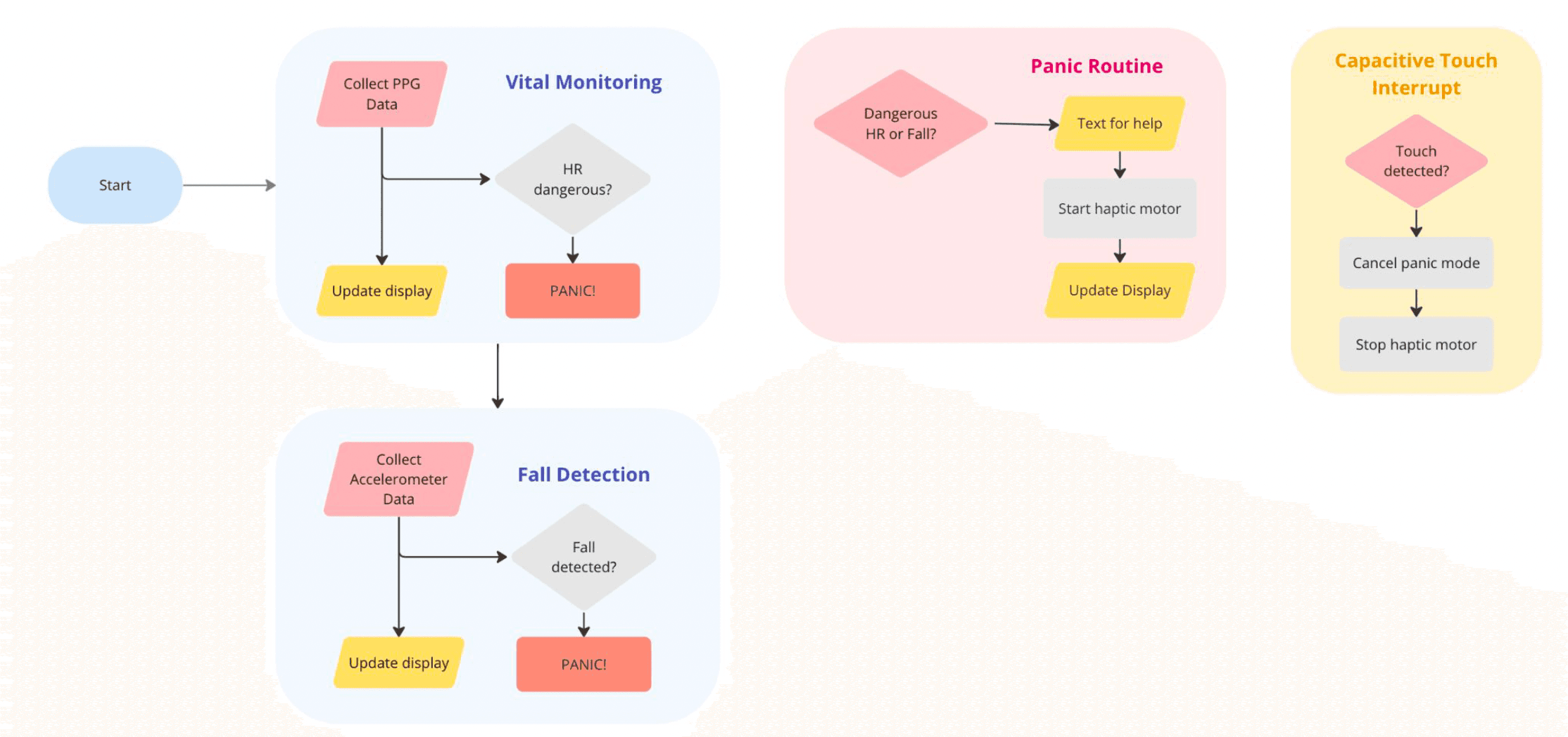
Fall detection — reads X, Y, and Z acceleration over I2C, applies an FIR filter to suppress everyday motion noise, and flags a fall when Z-axis acceleration crosses a set threshold.
Vitals monitoring — uses the PPG sensor to extract heart rate in real time. Values outside a healthy range from the accelerometer or the PPG sensor set a shared "danger" flag.
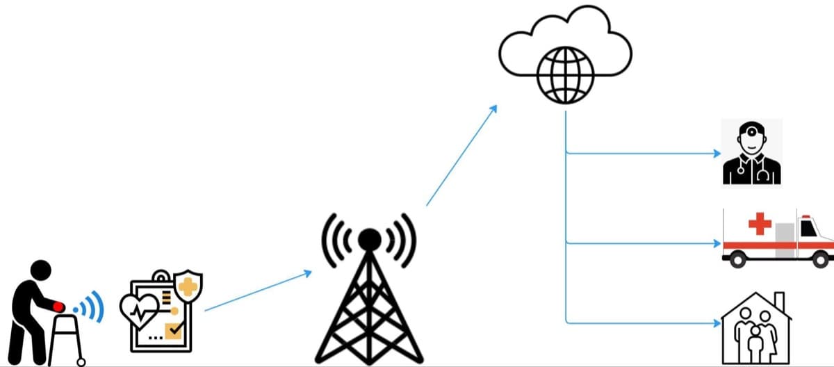
The panic routine — sends an SMS through Twilio over HTTP, starts the haptic motor, and updates the display. False alarms are cancelled with the capacitive touch sensor.
PCB and 3D-Printed Design
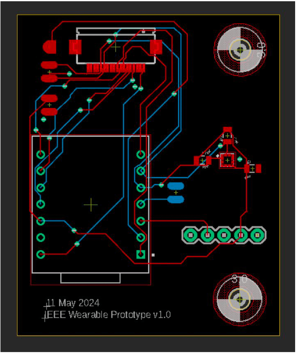
I designed and assembled a two-layer PCB, which became enclosed in a 3D-printed case sized to hold the board, sensors, and display in a wearable form factor.
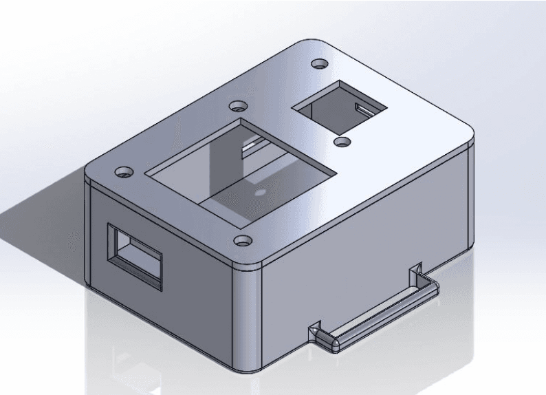
Debugging
Porting from prototype to wearable hardware: The system was first brought up on an ESP32 Feather (a larger, easier-to-wire dev board) before porting the firmware to the smaller SEED32 selected for the actual wearable form factor. The SEED32's default I2C pins didn't match the rest of the design, so the accelerometer bus had to be explicitly remapped to different SDA/SCL pins rather than relying on the board's default initialization.
Noisy PPG readings: We weren't able to use the sensor library's stock beat-detection logic to produce stable readings on the wrist. It took trial-and-error to land on a noise-sensitivity correction factor that gave reliable beat detection. Getting stable readings was challenging because of motion artifacts and variability in how the sensor sat against the skin. This issue became worse once the PCB was integrated into the wearable enclosure.
Verification
We tuned the fall-detection threshold using controlled drop tests and everyday activities like walking and climbing stairs. A 20-sample moving average filtered noise from the Z-axis accelerometer signal, which was then compared against a threshold of 25,000 raw counts. This value detected falls without triggering on normal motion.
The heart-rate reading is only trusted once the PPG sensor's IR signal confirms the sensor is actually against skin. When there is no contact, the display reports no reading rather than a noisy one. Once contact is detected, beat-to-beat estimates are averaged over a rolling 12-sample window and checked against a range of 60-120 bpm. A reading outside that range calls the panic routine.
Results
The full heart rate monitoring, fall detection, and panic sequence was demonstrated end-to-end on the ESP32 Feather dev board rather than the final wearable hardware. In the final SEED32-based PCB and 3D-printed enclosure, PPG signal-quality issues prevented reliable heart-rate measurements.
What's next
The next additions could be blood pressure sensing, IR or Bluetooth-based indoor localization (so an alert can include where the user is), audio feedback, and a battery power path so the device isn't limited to tethered operation.