Guide Glasses
Northwestern CE 347, Spring 2025
View code on GitHub ↗︎- Wearable Technology
- Embedded Systems
- Sensor Integration
- Assistive Technology
- AI Integration
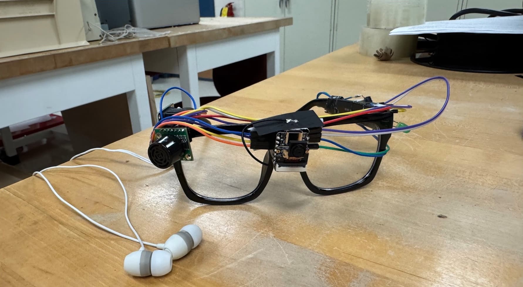
The problem
A white cane provides tactile feedback about the ground ahead, but it cannot detect obstacles above cane height or describe the broader environment. Guide Glasses is a pair of smart glasses meant to complement a white cane by adding scene description on demand and continuous obstacle detection above the waist.
System architecture
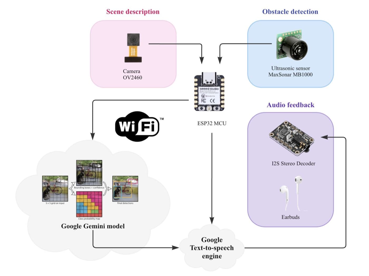
The system uses three main components:
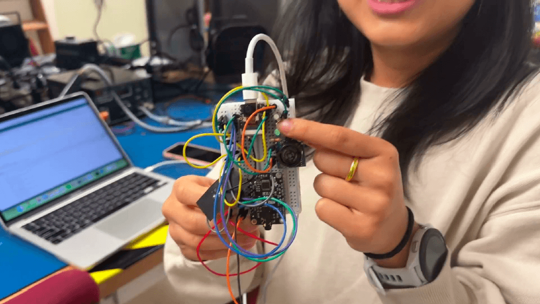
- Seeed Studio XIAO ESP32S3 Sense — MCU and camera
- MaxSonar MB1000 — ultrasonic obstacle sensing
- I2S stereo decoder — headphone audio output
Two features share the same MCU and audio path:
Scene description — a button press captures a JPEG frame, sends it over Wi-Fi to Google's Gemini model, gets back a natural-language description, converts that text to speech, and plays it through the I2S decoder into the user's headphones. Only one image is ever held in memory (an 80 KB buffer that gets overwritten on the next capture).
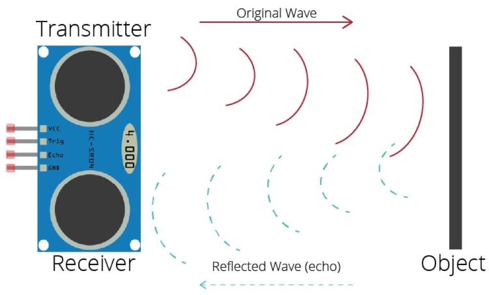
Obstacle detection — the ultrasonic sensor polls continuously at 10–20 Hz for anything within 3 feet in the upper-body zone. A detection triggers an "Obstacle Detected" audio clip through the headphones, and can be silenced with a cancel button.
Because these two audio paths can compete for the user's attention, the firmware gives obstacle-detection interrupts strict priority over scene description. This means an in-progress scene description can be cut off by an obstacle alert, but never the reverse.
Making the obstacle detection reliable
Filtering noisy sensor data
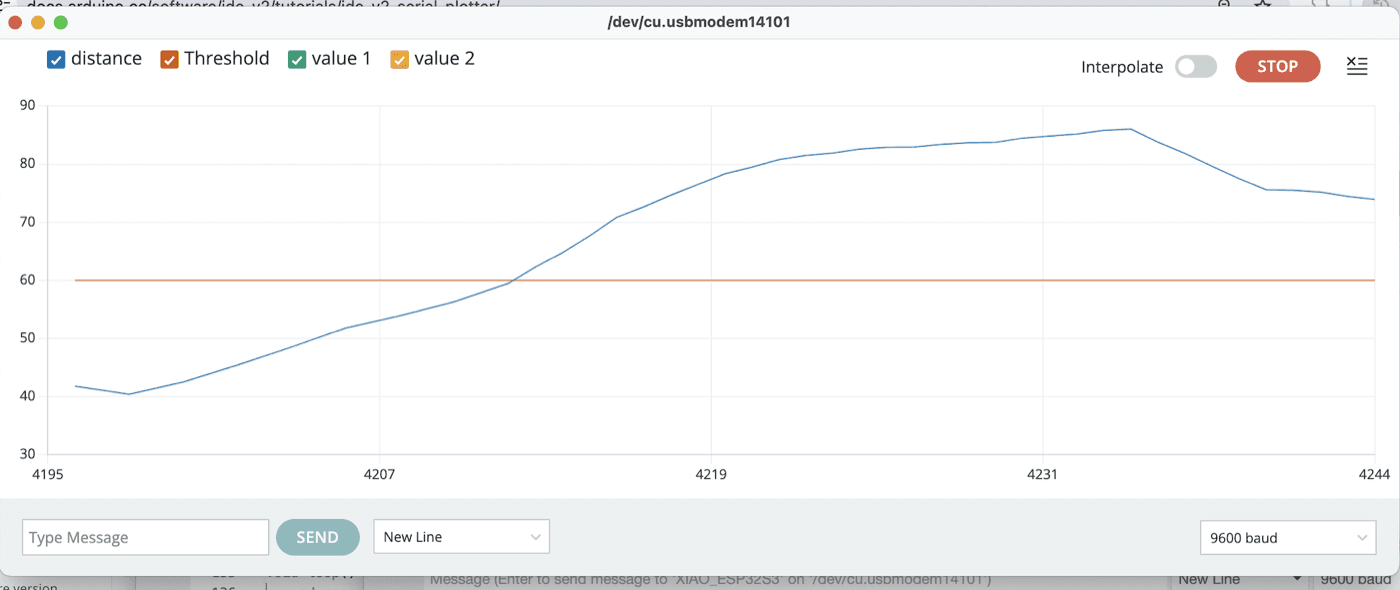
Without filtering, small variations in the ultrasonic readings could trigger inconsistent or false obstacle alerts. A moving average was applied across the five most recent readings on top of the sensor's existing low-pass behavior. This produced a more stable distance measurement before alert decisions are made.
Calibrating the detection range
I also calibrated the sensor using the datasheet's voltage-to-distance relationship and physical measurements from ~40-85 inches. A standard cane typically reaches about 3 feet ahead at a natural angle, so 3 feet became the obstacle-alert threshold.
Verification
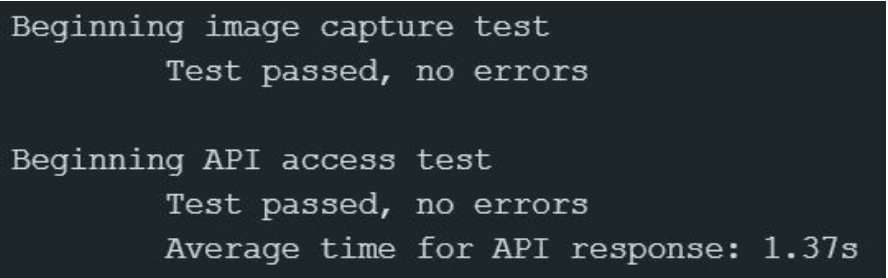
The system performed startup self-tests for each peripheral and results were logged over serial so failures could be identified immediately. The full camera-to-server workflow was verified through repeated capture-and-upload cycles, verifying that each image had a valid JPEG header and that the server returned a successful response.
Evaluating scene descriptions
We tested images containing cars, sidewalks, and roads. Different prompts were compared based on how consistently the returned description included expected information.
The simple prompt:
Describe this scene in one sentence performed more consistently than more verbose prompts, which tended to over-focus on specific hazards.
Measuring latency
End-to-end latency was approximately:
- 1.37 s from button press to audio on the ESP32
- 1.18 s for the same request from a Python script
The relatively small difference suggested that most of the delay came from image transmission and the model request, rather than the embedded hardware. Because of this, we kept the camera at the lowest resolution that still produced usable scene descriptions.

Ethical considerations
An LED lights up on the front of the glasses any time an image is being captured, so people nearby have a visible signal that a photo is being taken of them. On the reliability side, we explicitly discussed false negatives vs. false positives for a safety device: a missed obstacle is dangerous, while a false alarm is only inconvenient. Thus, the filtering and threshold choices were designed conservatively to prioritize detecting obstacles.
Results
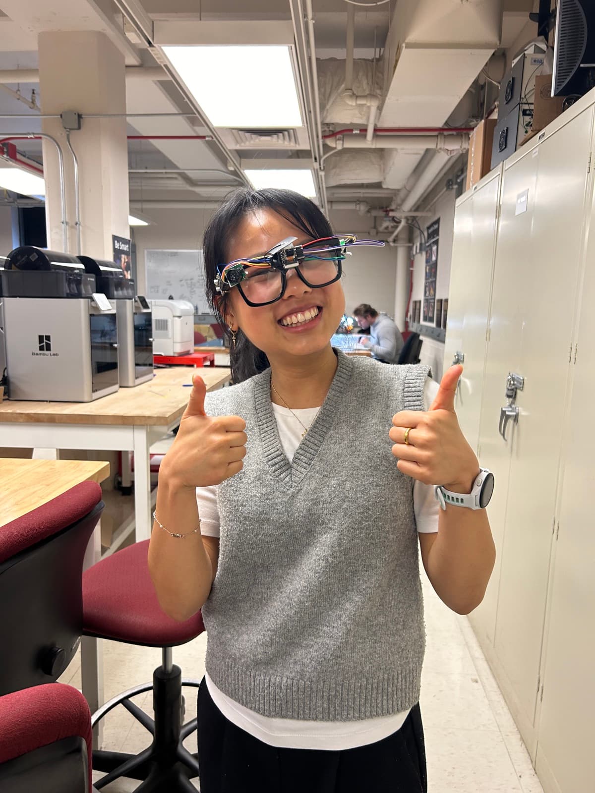
The completed prototype was tested while walking around in a lab environment. Obstacle alerts fired pretty reliably at the 3-foot threshold, scene descriptions returned usable output for the room scenes tested, and the interrupt priority behaved as designed. Testing so far has been limited to that indoor setting, so the system hasn't yet been validated against the more hazardous real-world cases it's ultimately meant for.
What's next
-
Real-world testing: Validate obstacle detection outdoors and around actual hazards (e.g. intersections, stairs, curbs) rather than only in the classroom/lab environment.
-
Battery and PCB: The prototype is currently tethered to a computer and has exposed wires. A future version would use a self-contained battery and custom PCB with improved wire management.
-
Address thermal behavior: The ESP32S3 warms up during continuous use. Thermal management and power optimization would be important in a wearable revision.
-
Expand accessibility features: Potential future features include voice control, on-device OCR, turn-by-turn navigation.